Camera Tracking of Aircraft Control Positions
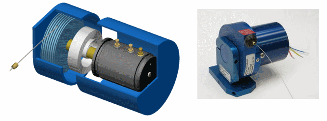
The standard method of tracking the aircraft’s control positions as the pilot moves the controls for flight test instrumentation (FTI) purposes is to attach string potentiometers (string pots) to the control cables/rods. As the control cable/rod moves based on the pilot’s inputs a spring loaded thin steel wire is reeled in or out of the string pot. The mechanical movement of the reel changes the electrical resistance resulting in a change in voltage output which is then measured and recorded by the FTI system.
In some cases though it would be ideal if you could track the aircraft control positions without having to physically attach a wire to the control cable/rod. So I developed a system to track the control positions using a web camera to track a target consisting of a piece of thin black card with two white circles.
In the following example in a Beechcraft King Air we’ve mounted the web camera on the instrument panel looking back at the yoke. The software detects the two white circles and tracks their position within the camera’s field of view.
![]()
To track the rotation angle of the yoke, i.e. to track the aileron deflection we can work out the angle between the centers of the two white circles. To track the elevator deflection we track the movement of the yoke in and out of the instrument panel by tracking the change in diameter of the circles, or the distance between the two circles. As the yoke is pushed forward the circles appear larger and vice-versa as the yoke is pulled back.
In this particular calibration screenshot the aileron deflection is displayed as 47.81%, i.e. there is a slight rotation, 50% would indicate no rotation of the yoke. The elevator position is listed as 82.65% where 50% would indicate the yoke is centered in terms of fore and aft movement and 100% would indicate the yoke has been pulled back fully.
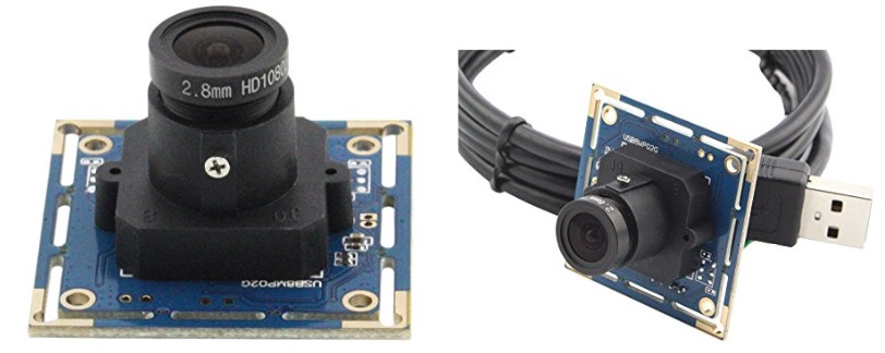
This is the USB web camera that we used. You can get a feel for it’s physical size by comparing it to the size of the USB plug. What was very useful was the replaceable lens which meant we could use different lenses based on their field of view depending on the particular aircraft type in terms of the physical spacing between the camera and the target.
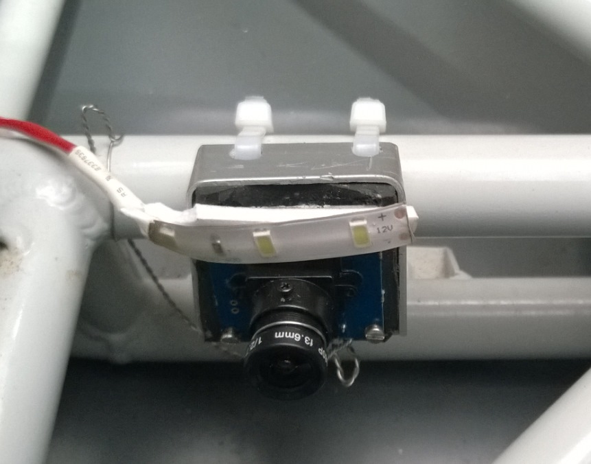
One of the initial issues we ran into was the jello effect in the video stream from a combination of the vibration that the camera experiences and it’s use of a rolling shutter. So we mounted the cameras in a housing we made up in which we included anti vibration foam, the black foam material you can see in the photo below.
For aircraft that don’t have a yoke but have a joystick instead we mount the cardboard target on a control cable/rod and then mount a camera to track the linear movement of the target as the control cable/rod moves. We typically have to also do this for the rudder in aircraft with a yoke as well.
The following photo shows the cardboard tracking targets mounted in an Extra-300 aircraft, with one on a control rod for the elevator and one on the rudder control cable. You can just make out the camera mounted to track the rudder control cable movement in the top right of the photo.
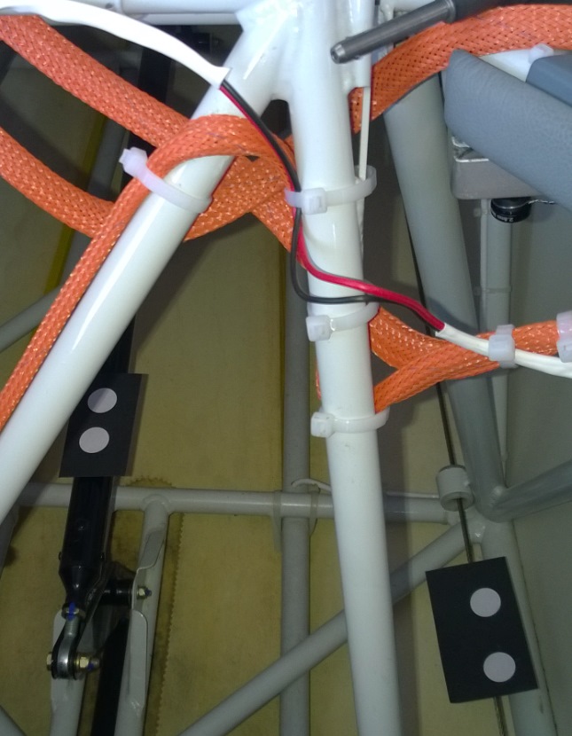
The software to perform the circle detection from the 1080p USB web camera ran on an ODROID single board computer. It would process each frame to detect the location of the circles and then using the calibration data for the particular target it would then output the control position data to the FTI system where it would be recorded and displayed in real-time.
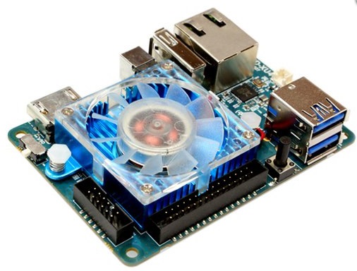
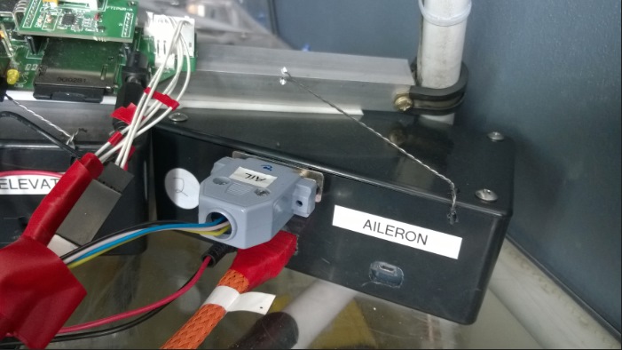
The ODROID in it’s enclosure mounted in the Extra-300.
The biggest issue we faced with the camera tracking system was due to lighting conditions. In particular for the installations mounted in the cockpit tracking a yoke we ran into issues where the camera’s automatic gain control couldn’t deal with large and quickly changing lighting conditions based on the sun shining into the cockpit as the aircraft maneuvered.
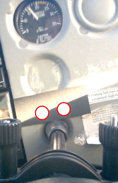
In the example screenshot below the system can still detect and track the two white circles. However as the sun moves further down the white circles will disappear. In most of these sorts of installations we built a small cardboard shroud to prevent direct sunlight hitting the target area. However the ideal would be to use a camera with a high or at least very wide dynamic range.
For installations where the target was mounted on a control cable/rod and away from direct sunlight we never ran into issues with losing the target for brief moments. In general in these installations we installed some LED lighting to give us a fairly constant lighting condition. In the photo above of the camera mounted with anti vibration foam you can see a short strip of 3 LEDs to provide lighting from the camera aimed at the target.
For an example of the data collected using this system take a look at the Extra-300 Spin article.
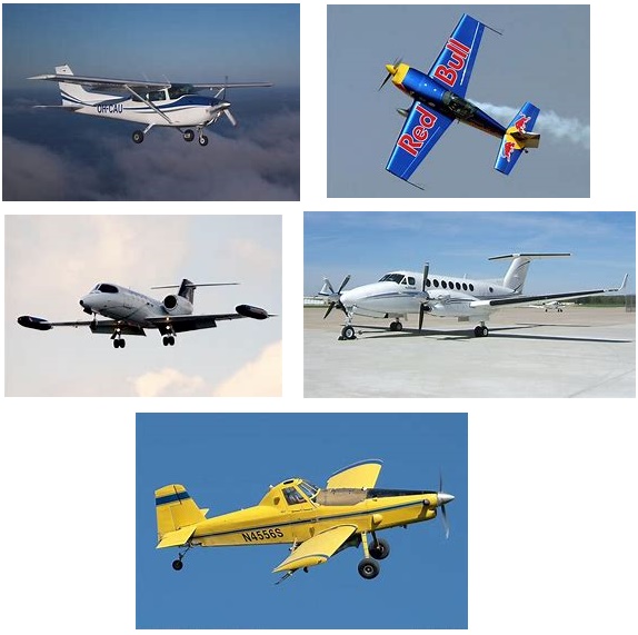
So far we’ve installed and used this system in the following aircraft - Cessna 172, Extra-300, Learjet, King Air, and AirTractor.