Geeks and Fast Jets
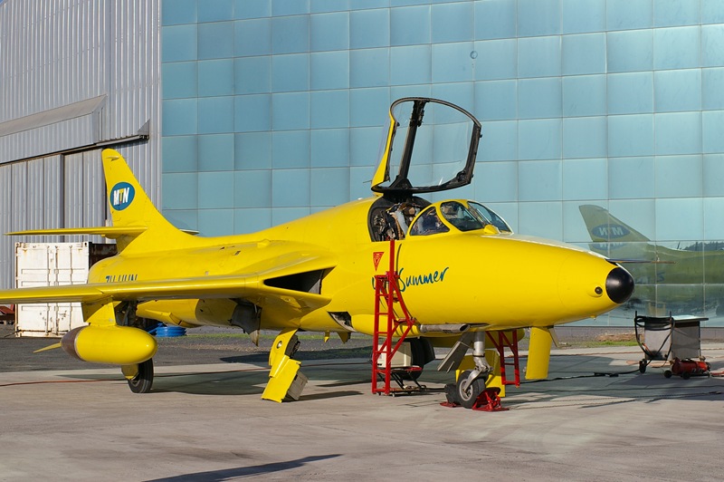
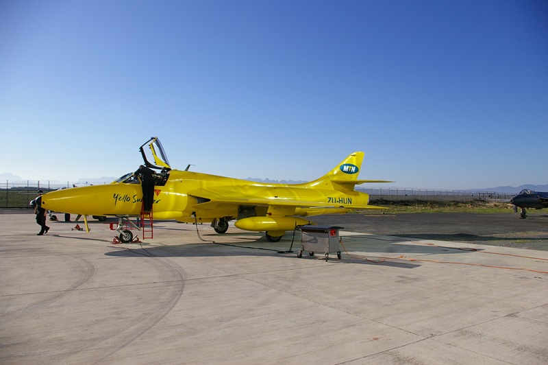
I was approached recently to help develop some Flight Test Instrumentation (FTI) for a Hawker Hunter jet to be used during a test pilot course involving high angle of attack manoeuvres and spinning.
The following data needed to be recorded:
- Angle of Attack (AoA)
- Angle of Sideslipe (AoS)
- Attitude (pitch, roll and heading)
- Indicated airspeed and altitude
- Stick and rudder position
- GPS
- Video
In addition to recording all the data listed above they also wanted to display a subset of the data in the cockpit as an aid for spin recovery.
Sensors
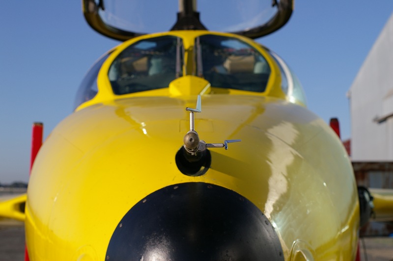
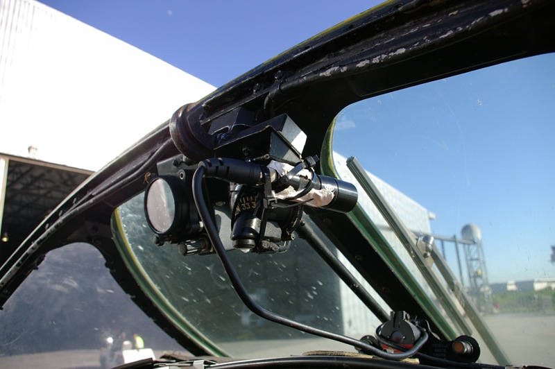
AoA and sideslip - basically small weather vanes that act as potentiometers were ordered and then physically mounted on a pitot/static boom which was then mounted on the front of the Hawker Hunter’s nose. One minor issue was finding a route for the wires from the vanes to the PC in the avionics bay that didn’t have to pass through the cockpit’s pressure capsule.
Attitude - ordered an Attitude and Heading Reference System (AHRS) from Crossbow that uses solid state sensors and outputs at 25Hz. Ideally the AHRS needs to be mounted as close as possible to the centre of gravity. Luckily the avionics bay is fairly close to the centre of gravity, just slightly forward but there was space to mount it quite easily and definitely on the centre line of the aircraft.
GPS - the Crossbow AHRS also includes a built-in GPS which it uses for aiding it’s attitude solution and also outputs standard NMEA data via a second serial port. Mounted the GPS antenna on the spine of the aircraft behind the cockpit with a fairly short vertical run for the GPS antenna cable to the avionics bay.
Air data - used an existing unit we had from MGL Avionics that we had been using on the Ikarus C-42. Wasn’t ideal since it’s maximum indicated airspeed is 217kt which means it was maxed out a lot of the time. However the stall speed was generally below 217kt so it did provide useful data during the stall and spin.
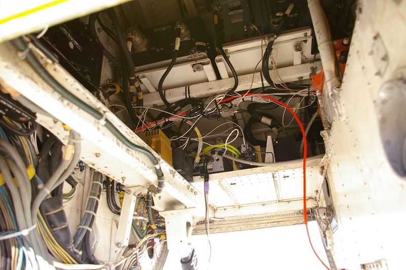
Control positions - we ordered 3 linear transducers which basically have a shaft that moves in and out and it acts as a potentiometer. They were mounted and attached to the 3 control rods that pass through the spine of the aircraft behind the cockpit. It was again a fairly short straight drop down into the avionics for the wires.
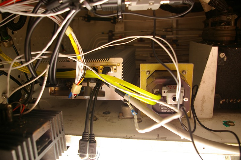
PC
We needed a PC on fairly short notice that was fairly ruggedized in terms of handling vibration and also fairly cold operating temperatures since it was going to be mounted in an unpressurized and unheated avionics bay and the spins would normally be starting at 35,000ft.
The only real change we made to the embedded PC we found was to replace the hard drive with a CF card and to run everything off the CF card. In addition to the high dynamics during the spin plus regular vibration causing problems for a normal hard drive most hard drives aren’t rated to operate above 10,000ft pressure altitude anyway.
We used XP Embedded and it’s Enhanced Writer Filter (EWF) to turn the system partition into a read-only volume so it couldn’t be corrupted during power down since the power was simply going to switched off with no proper shutdown. The data from the sensors was logged to a separate partition on the CF card.
The embedded PC also came with 4 onboard RS232 ports which we needed in order to connect to all the RS232 based sensors (AHRS, GPS, air data). To read the analog data from the AoA, sideslip and control position sensors we installed an A/D card into the single PCI slot.
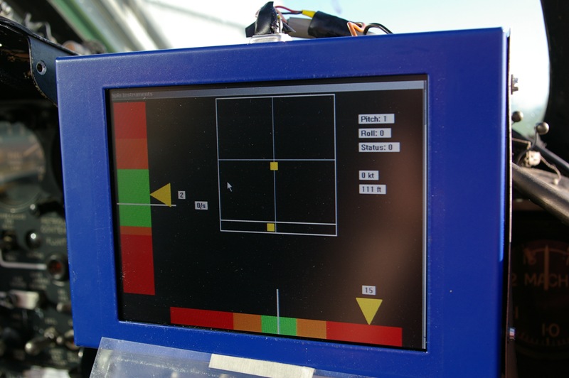
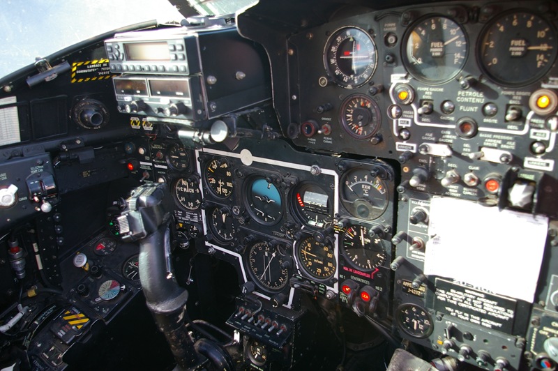
Display
For the in cockpit display of ‘spinning panel’ which mainly consisted of displaying the AoA and sideslip angles plus the control positions we initially developed a Pocket PC application which was connected to the embedded PC via an RS232 connection. However after some concerns regarding it’s sunlight readability and some concerns about physically mounting it in the cockpit the Pocket PC was only used on 2 initial test flights.
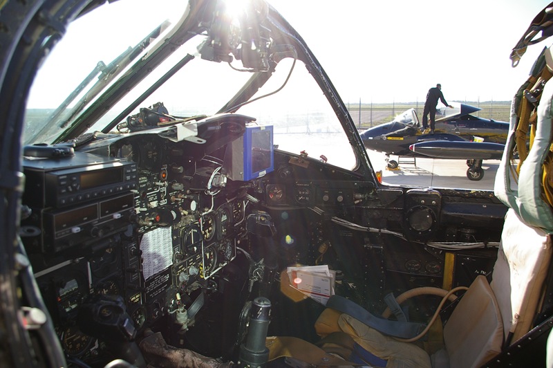
We then bought a 6" LCD which was rated at 1200nits for sunlight readability and removed the gunsight to mount the LCD in it’s place on the student’s side of the cockpit. The software for the ‘spin panel’ was then modified to run on the embedded PC that we were using for data capture and to connect it to the LCD using a VGA connection.
The one issue or complication with the ‘spin panel’ display being mounted in the cockpit was the need to have wires passing through the pressure bulkhead from the avionics bay into the cockpit. Special bulkhead connectors have to be used in order to pass the wires through without causing a pressure leak.
Video
An SD based video camera recorder with a remote lens was mounted in the cockpit and used to capture video footage of the flight.
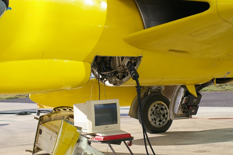
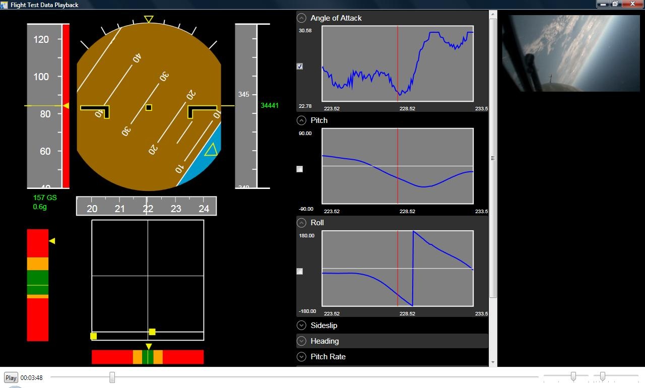
Playback
The last part of the project involved the development of a playback system to take the captured data from the sensors and from the video camera and allow the data to be played back and analysed by the pilots and flight test engineers.
The attitude data and air data are displayed as part of a standard Primary Flight Display (PFD). The spin panel display that is used in the cockpit is also rendered plus playback of the video. Lastly we have line graphs displaying the current, past and future data for each of the recorded parameters.
All of the data including the video is synchronised during playback and can be paused, seeked and played back at different speeds, i.e. various slow motion and fast motion playback speeds. The playback application is a Windows Presentation Foundation (WPF) application and makes heavy use of the animation framework within WPF.
And finally getting ready for the last of the 34 sorties on a glorious Cape Town winter’s day.